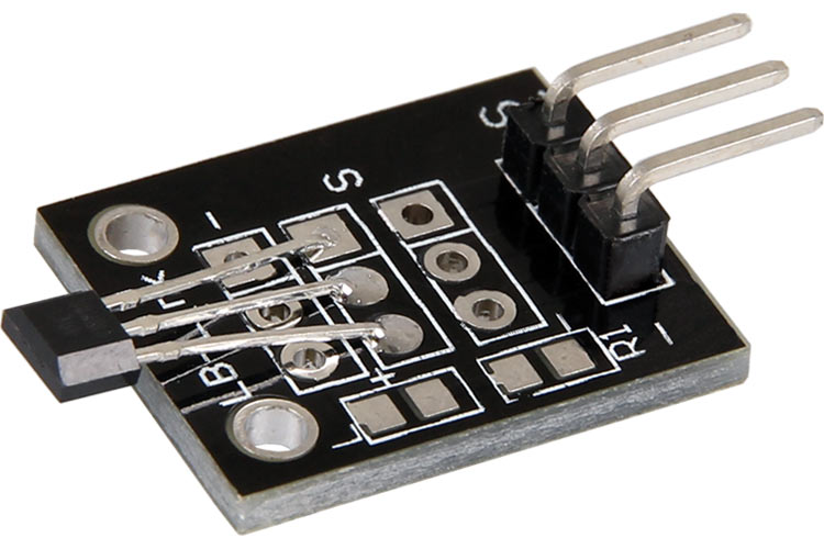
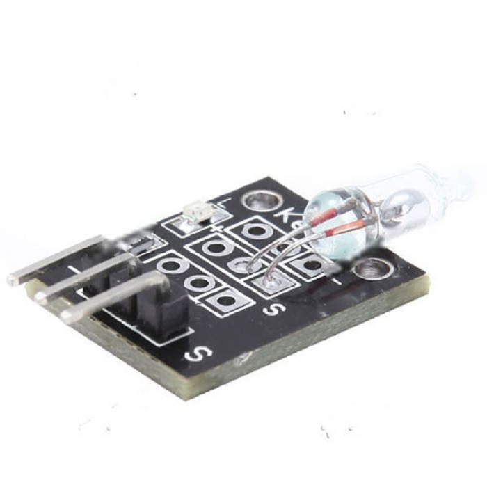
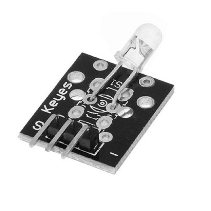
ماژول سنسور مغناطیسی (اثر هال ) KY-035
- پارت نامبرKY-035
- سازندهنامشخص
- مدلModelKY-035
- توان ورودیInput Power5V
- نوع ورودیInput TypeAnalog output
فهرست مطالب
- مشخصات فنی ماژول سنسور اثر هال آنالوگ
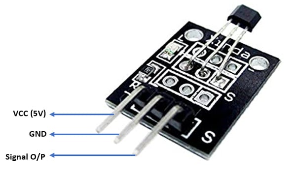
- پایه های ماژول سنسور اثر هال آنالوگ
- دیاگرام اتصالات
- کدهای آردوینو
- کدهای Raspberry Pi
توضیحات
KY-035 یک ماژول سنسور اثر هال آنالوگ است. قدرت میدان توسط ولتاژ آنالوگ در پین سیگنال ماژول KY-035 داده می شود.
مشخصات فنی ماژول سنسور اثر هال آنالوگ
مشخصات ماژول در جدول زیر آمده است:

پایه های ماژول سنسور اثر هال آنالوگ
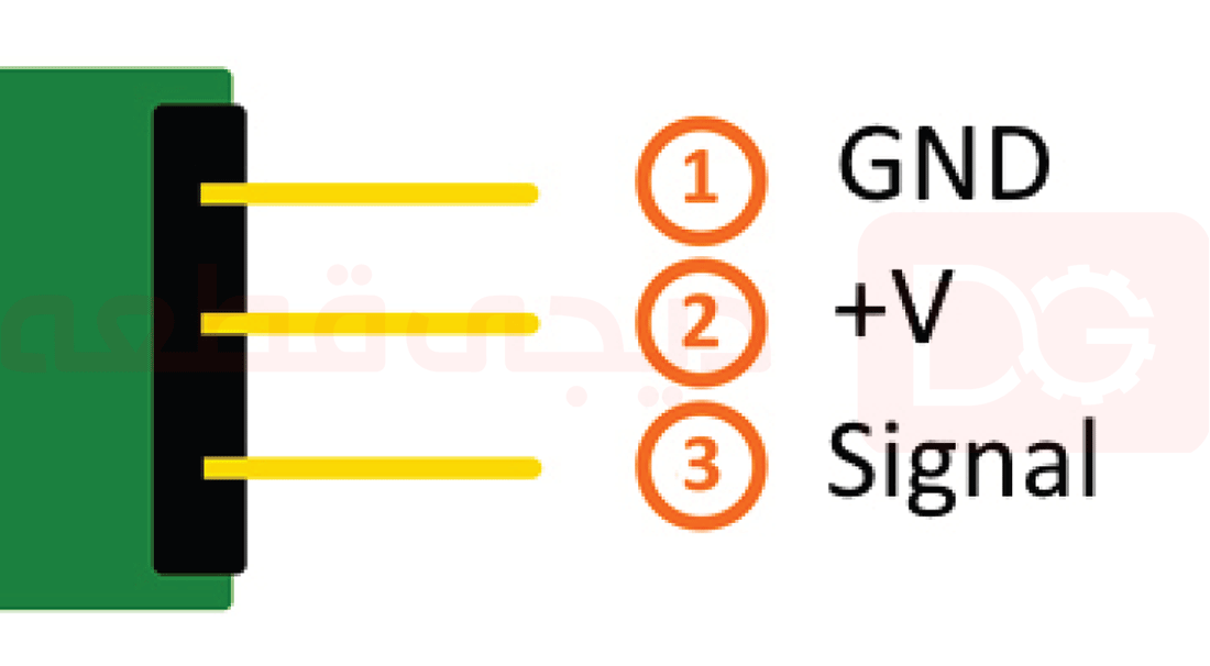
اتصال پایه های ماژول در برد Arduino و Raspberry Pi در جدول های زیر آورده شده است:

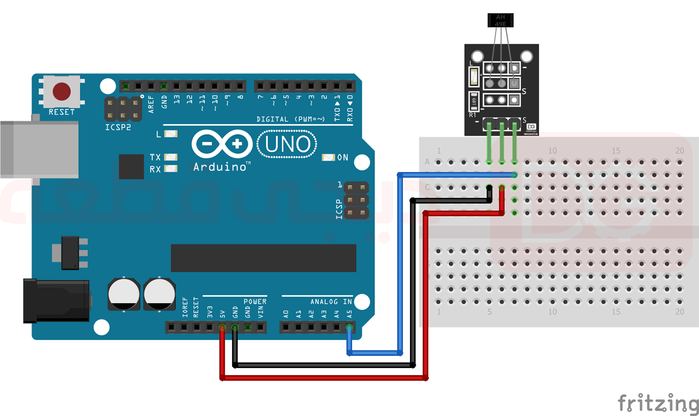
دیاگرام اتصالات ماژول KY-035
پایه های مختلف ماژول را مطابق جدول بالا و به صورت آنچه در تصویر زیر مشاهده میشود به برد آردوینو متصل کنید.
کدهای آردوینو KY-035
کد زیر ولتاژ خروجی سنسور را اندازه می گیرد و مقدار نمایش داده شده درمانیتور سریال آردوینو را نشان می دهد.
int sensorPin = A5; // Declaration of the input pin

// Serial OUT in 9600 baud
void setup()
{
    Serial.begin(9600);
}

// The program measures the current voltage at the sensor,
// calculates the resistance with it and a known resistor
// and outputs it via serial OUT

void loop()
{
        // Measuring of the current voltage...
    int rawValue = analogRead(sensorPin);
        float voltage = rawValue * (5.0/1023) * 1000;

        float resitance = 10000 * ( voltage / ( 5000.0 - voltage) );

    // ... output via serial interface
    Serial.print("Voltage:");   Serial.print(voltage); Serial.print("mV");
    Serial.print(", Resistance:"); Serial.print(resitance); Serial.println("Ohm");
    Serial.println("---------------------------------------");

    delay(500);
}
کدهای Raspberry Pi KY-035
Raspberry PI برخلاف آردوینو، مبدل آنالوگ به دیجیتال (ADC) را در تراشه خود ارائه نمی دهد. بنابراین اگر از سنسور غیر دیجیتال استفاده کنید، Raspbery Pi محدود می شود. برای اجتناب از این موضوع از ماژول هایی که یک ADC 16 بیتی را ایجاد می کنند مانند ماژول KY-53 استفاده می کنیم تا آن را با 4 پین ورودی آنالوگ اضافی ارتقا دهیم. ماژول KY-035 از طریق I2C به Raspberry Pi متصل می شود. داده های آنالوگ را اندازه گیری کرده و آن را به یک سیگنال دیجیتال مناسب برای Raspberry Pi تبدیل می کند. بنابراین اگر می خواهید از سنسورهای آنالوگ به همراه Raspberry Pi استفاده کنید، از KY-053 ADC استفاده کنید.
اتصال پایه های ماژول در برد Raspberry Pi در جدول های زیر آورده شده است:

# This code is using the ADS1115 and the I2C Python Library for Raspberry Pi
# import needed modules
import time, signal, sys, os
import RPi.GPIO as GPIO
GPIO.setmode(GPIO.BCM)
GPIO.setwarnings(False)

# initialise variables
delayTime = 0.5 # in Sekunden

# assigning the ADS1x15 ADC

ADS1015 = 0x00  # 12-bit ADC
ADS1115 = 0x01  # 16-bit

# choosing the amplifing gain
gain = 4096  # +/- 4.096V
# gain = 2048  # +/- 2.048V
# gain = 1024  # +/- 1.024V
# gain = 512   # +/- 0.512V
# gain = 256   # +/- 0.256V

# choosing the sampling rate
# sps = 8    # 8 Samples per second
# sps = 16   # 16 Samples per second
# sps = 32   # 32 Samples per second
sps = 64   # 64 Samples per second
# sps = 128  # 128 Samples per second
# sps = 250  # 250 Samples per second
# sps = 475  # 475 Samples per second
# sps = 860  # 860 Samples per second

# assigning the ADC-Channel (1-4)
adc_channel_0 = 0    # Channel 0
adc_channel_1 = 1    # Channel 1
adc_channel_2 = 2    # Channel 2
adc_channel_3 = 3    # Channel 3

# initialise ADC (ADS1115)
adc = ADS1x15(ic=ADS1115)

# Main Loop

# Reading the values from the input pins and print to console

try:
        while True:
                #read values
                adc0 = adc.readADCSingleEnded(adc_channel_0, gain, sps)
                adc1 = adc.readADCSingleEnded(adc_channel_1, gain, sps)
                adc2 = adc.readADCSingleEnded(adc_channel_2, gain, sps)
                adc3 = adc.readADCSingleEnded(adc_channel_3, gain, sps)

                # print to console
                print "Channel 0:", adc0, "mV "
                print "Channel 1:", adc1, "mV "
                print "Channel 2:", adc2, "mV "
                print "Channel 3:", adc3, "mV "
                print "---------------------------------------"

                time.sleep(delayTime)


except KeyboardInterrupt:
GPIO.cleanup()کارشناسان ما آماده پاسخگویی به شما هستند.


